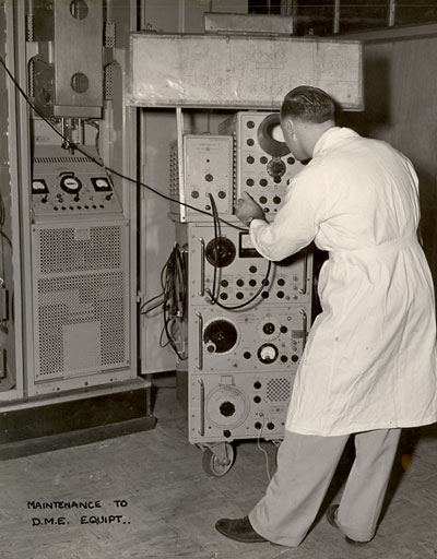
As with all radio navigation aids, regular inspection and testing is required to ensure that the aid is functioning correctly. The photos on this page show typical maintenance scenes for the Australian DME system. The equipment is an Amalgamated Wireless Australasia (AWA) DM3.
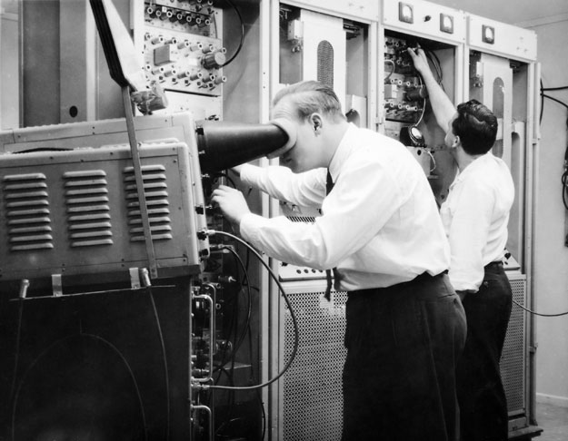
The photo above was taken in Brisbane, whilst the photo below was taken in Sydney. The identities of the technical officers are not known.
In the photo above, the technical officer is at the testmobile, peering into the CRO (cathode ray oscilloscope), examining waveforms and timing circuits. Note the long circuit diagram mounted above the CRO. The cabinet in view contains the transmitter: the pulse circuits are in a cabinet to the left, out of view. The white dust coat is indicative of the 1960s.
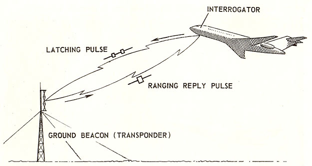
A novel feature of DME, when introduced, was that it was a pulse system. Of prime concern was that the beacon did not trigger with echoes caused by reflections from hills, etc. Another feature was the ability for more than one aircraft to interrogate the beacon at the same time. The two 'latching' pulses generated by the aircraft DME interrogator (reply and ranging) had to arrive within a certain range of time for them to be a valid signal. The testmobile allowed the technician to observe the behaviour of the unit's internal circuits at different points by feeding in simulated interrogation pulses. As a check on the system's self-monitoring capability, the technical officer would also be adjusting pulse widths and spacing beyond the prescribed limits to see that an alarm condition resulted.
Read more about how the system worked here
The photo below shows a 48-channel DME, so the photo must have been taken after 1966. Again, well dressed gentlemen.
Click here to see an external view of the installation
(Photos: CAHS collection)
Back to the main Communications and Navigation Index
If this page
appears without a menu bar at top and left, click
here