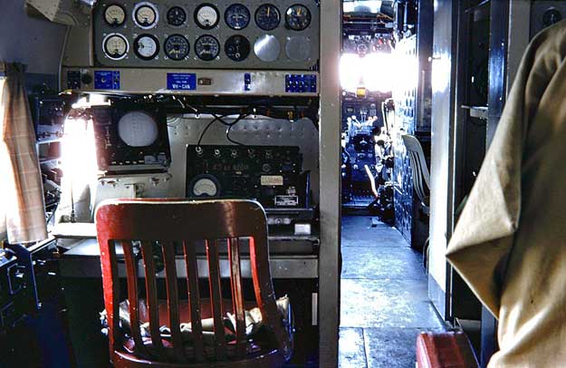
Above: The port Flight Surveyor station, looking forward, aboard DCA
DC-3 VH-CAN c.1959. The survey electronics
were kept in racks between the flight deck and cabin.
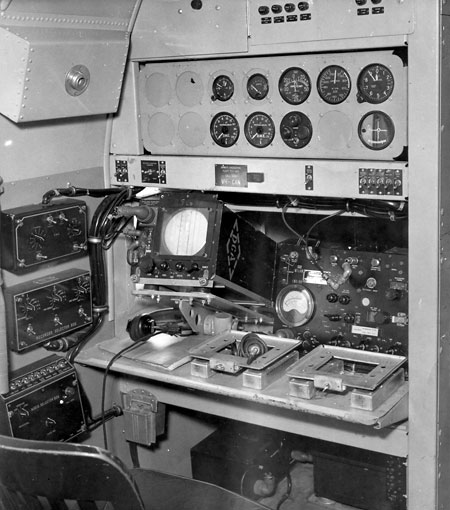
The instruments in the top panel are, from left to right in the upper row: two high voltage voltmeters; clock; voltmeter for the aircraft's 28V electrical system; Outside Air Temperature; Air Speed Indicator; Altimeter. In the bottom row, L-R: Localiser; Glidepath; two DME(A)s; Marker receiver for Airways, Outer and Middle Markers; two blanks. The Cathode Ray Oscilloscope (CRO) is for a Rebecca receiver, used for DME checks. The box to its right is Rebecca test gear, used to check the aircraft's systems and rarely fitted. To the Surveyor's left below the window sill are audio control boxes for the aircraft's intercom system.
The following story was compiled by Doug Gillison, DCA Public Relations, for the November 26, 1946 issue of Interavia magazine:
FLYING
LABORATORIES
"The Department of Civil Aviation is converting two C-47 aircraft
[later VH-ASD & VH-DMV],
purchased from American disposal authorities, for service in checking
and calibrating the Department's existing VHF radio range network [Lorenz
33 MHz beacons]; testing new four-course VHF range [VARs]
now being installed and experimenting with advanced electronic equipment
on the multiple track radar range now being developed by the Commonwealth
Council for Scientific and Industrial Research [the fore-runner of the
CSIRO]."
"Aircraft will also be used for testing pilots for commercial licences and inspecting remote outstations."
"Modifications
include duplication of all engine instruments at the flight engineer's
desk. In addition to a normal communication transmitter operating on eight
frequencies with duplicate emergency unit directly controlled by radio
operator, installation of equipment includes:- VHF transmitter and receiver
for airport and airways control; pilot's remotely controlled receiver
for medium or high frequency work, special 33 MHz radio range receiver
for use with the Department's existing chain of transmitters; VHF radio
range receiver for new 112-118 MHz 4-course radio range equipment now
being tested; automatic radio compass to give aircraft's heading in relation
to any radio beacon or broadcast station; localizer instrument approach
receiver giving lateral indication of aircraft's position when coming
in on SCS-51 ILS; glide path instrument approach receiver giving vertical
position when landing on SCS-51;
radio altimeter; radar distance indicator [DME]; multiple track radar
receiver; American Signal Corps' 'LORAN' long range aerial navigation
receiver; inter-com. system connecting all crew positions."
(Photos: CAHS collection)
Click here to see a photo of a DCA DC-3 on ILS calibration work.
Back to the main Departmental DC-3 index
If this page appears without a menu bar at top and left, click
here