In the late
1940s DCA commenced a series of experimental
radar installations at Melbourne/Essendon with a wartime Light Weight
Air Warning (LW/AW) radar installation. Click here to see
and read more about this installation.
The LW/AW set was developed in 1942 in Australia by the Council for Scientific and Industrial Research (later CSIRO) Radiophysics Laboratory in response to the need for a portable air defence radar station that could be readily deployed in northern Australia, New Guinea and the islands to Australia's north.
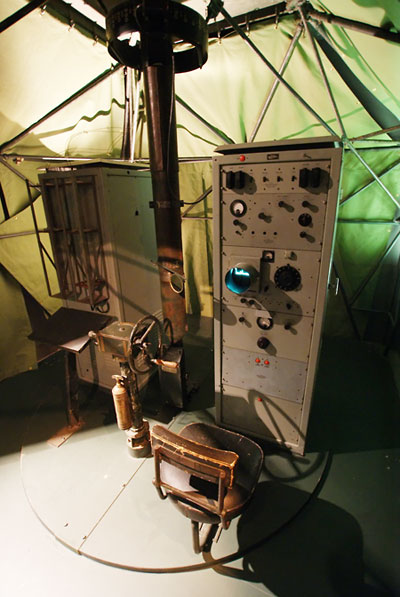
To facilitate deployability, the radar equipment and operator were housed in a canvas tent and the photos on this page show the internal layout. The operator, transmitting equipment and antenna all sat on a rotating platform which the operator turned by hand, thus changing the direction of view of the set. The operator's display was a small cathode-ray tube 'A-scope' (range-only display). The physical orientation of the antenna, read off a bearing scale at the top of the antenna shaft, gave the direction of target returns.
One advantage of this method of operation for air defence purposes was that the radar could either be used in search mode, by scanning back and forth through an arc or all around, or in track mode by continuously 'looking' at a particular return of interest, or in a combination of both modes.
Roll your cursor over the image above to identify components of the LW/AW system. The photo shows an LW/AW displayed in the Australian War Memorial on 28 June 2010.
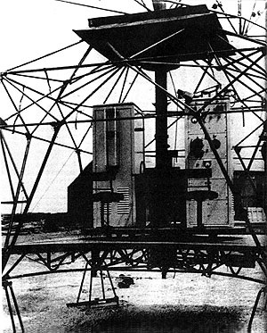
Left: This photo shows the LWAW radar with the covering tent removed. The electronics cabinets, operators' positions and antenna were all mounted on an elevated, rotating platform.
(Photos: Top-Phil Vabre; Bottom-CAHS collection)
The LWAW was designed to be a highly portable system, breaking down into numerous small components. The series of images below, taken from a set of RAAF instructional images in the CAHS collection, shows how the unit could be broken down for transport.
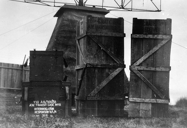
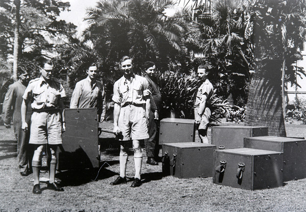
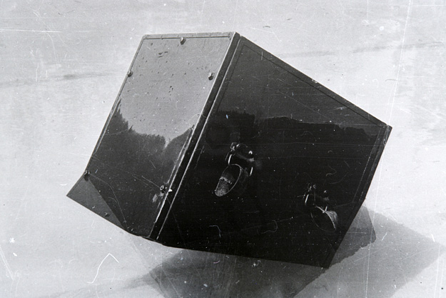
Above and below: An assembled LWAW with the electronics broken down for transport. In the upper image the transmitter and receiver cabinets are packaged whole in the large crates. In the image below the electronics cabinets are broken down into smaller crated packages.

The design requirement for the LWAW was that no component must weigh more than 80 lb (36.2 kg) and the largest piece must be able to pass through the door of a DC-2 or the blister of a Catalina.
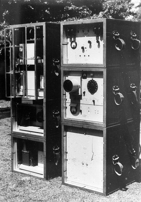
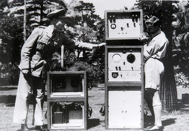
The image at left shows the two electronics cabinets, transmitter on the left and receiver on the right, assembled as they would be in operation.
The images beneath show the cabinets being disassembled into their component units for transport.
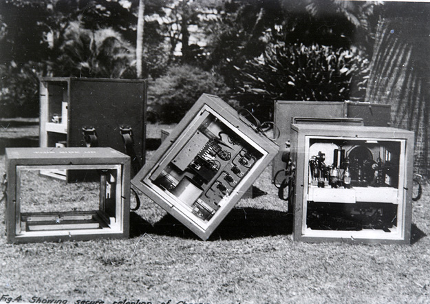
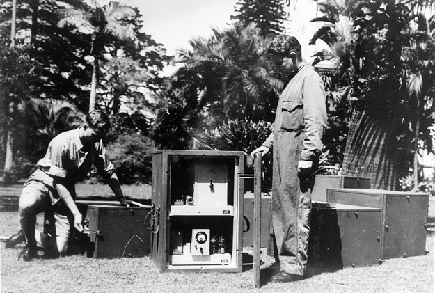
The image above shows the transport ends being fitted to the electronics units and, below, the units packed and ready for transport. The straps on the side of each case made the units readily man-portable.
Below: When packed for transport, the cases were designed to float if accidentally dropped in water.
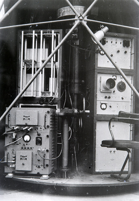
Left and below: The electronics cabinets assembled and ready for operation. The image at left shows the operator side of the unit with the operator's seat at right in front of the A-scope CRT on the receiver cabinet.
To the operator's left is a handwheel used to manually traverse the antenna. At the top, the bearing scale can be seen.
On the left hand side is the transmitter cabinet.
The image below shows the electronics cabinets from behind. Prominent is an electric blower for cooling the transmitter electronics.
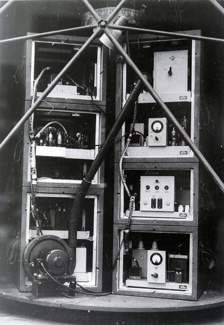
(Photos: RAAF via CAHS collection)
Back to the main Communications & Navigation Index
If this page appears without a menu bar at top and left, click here