Roger Meyer describes this revolutionary and pioneering Australian navigation aid of the 1940s.
Background
During the Second World War, the Council for Scientific and Industrial Research (CSIR) – the forerunner of today’s CSIRO – established a Radiophysics Division to conduct research and development work, particularly on radar equipment for the armed services. After the war the staff and the work of the Division changed considerably and a balanced programme of pure and applied research was started. A proportion of the work consisted of applying the techniques developed for wartime use to civil needs. Perhaps the most important applied work was in the development of navigational aids for civil aviation.
Under the aegis of the CSIR, the Aviation Radio Research Committee was formed, with representatives from CSIR, DCA, the PMG’s Department, the RAAF, the Australian Air Pilots Association, Qantas Empire Airways Ltd. and Australian National Airways Pty. Ltd. The function of the Committee was to advise the CSIR of the directions in which development work should be undertaken. It recommended adoption of two of the four main projects which Australia had undertaken to investigate at the Commonwealth and Empire Conference on Radio for Civil Aviation (CERCA) in 1945.
In recent years the density of civil air traffic in many countries had become so great that the problem of handling traffic and avoiding congestion at main airports had become serious. It was generally acknowledged that that the situation would be improved if a simple and accurate method of navigation existed in the vicinity of airports. The method of short-distance navigation that received most support at CERCA and PICAO conferences in 1945-46 was the “Rθ” (rho-theta) system, which gave distance and bearing information from a selected point. Means existed for obtaining distance measurement on simple radar equipment that had been developed during the war. One of the several schemes that had been suggested for providing bearing information was the Multiple Track Range. It was a pulsed hyperbolic system, similar to the Gee and Loran systems that had been developed during the war. It was simple to operate, accurate, easy to fly and not subject to the siting and polarization difficulties favound in C.W. (continuous wave) systems.
Australia decided to adopt development of MTR, and to demonstrate it to the Radio Technical Division of PICAO in Canada during October 1946, at which time other member States also demonstrated possible navigation systems. The purpose of these demonstrations was to help in reaching agreement as to the international standards to be adopted.
The project comprised:
a) The development of a Radar Distance Indicator, the purpose of which was to permit an aircraft in flight to determine its distance at any particular moment from ground stations (this was later known as DME).
b) A Multiple Track Radar Range which, by the application of radar principles, defined tracks in space along which aircraft may fly.
Existing forms of radio ranges provided only a few tracks. The need was for an omni-directional range, providing a large number of straight tracks radiating from a centre. Such a range would be particularly suitable for use at busy traffic centres, with aircraft arriving and departing in various directions. The requirement, then, was for an omni-directional range in conjunction with distance measuring equipment, and a number of solutions had been proposed. The three systems that had been sufficiently developed to allow serious consideration were:
- The “Gee” system
- The “Omni” range of the U.S. CAA (better known as VOR)
- The Australian Multiple Track Radar Range.
Operation
The Australian MTR was a hyperbolic, short-distance navigation aid, providing up to 66 flight tracks into and out of an air terminal.
Ground Stations
The ground system consisted of two pulse transmitters. The master transmitter, M, emitted a series of pulses which were received by the slave station, S, and retransmitted a short time afterwards. An aircraft at any point first received the pulses from the master, followed by a pulse from the slave. Discrete values of the time interval between the master pulse and the slave pulse were used to define lines of constant time interval, which were hyperbolic in shape. These lines of constant time interval were the 'tracks'.
The master station pulse was preceded by another pulse and the time interval between these two pulses identified the master station (and its slave station). The aircraft control box provided a switch by means of which any one of six station pairs, in the same vicinity, could be selected. The number of tracks generated by any pair of ground stations depended on the spacing of the stations. A station spacing of 3.1 statute miles would generate 66 courses, but at Mascot the spacing was 1.7 statute miles which provided 19 tracks on each side of the baseline.
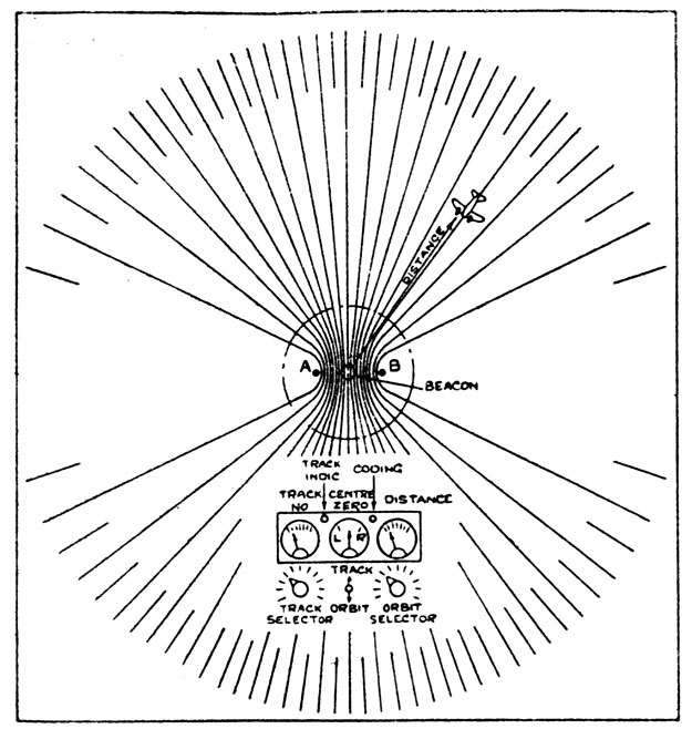
Above: Diagram showing the hyperbolic ‘tracks’ produced by the MTRR. The ground station comprised Master (A) and Slave (B) transmitters. Note the unusable sectors on either side of the Master-Slave axis. Although hyperbolic, outside of a short distance from the ground station the tracks were effectively straight lines.
Siting of Ground Stations
Since the tracks were defined in terms of the difference in time of the propagation of radio waves and not in terms of the amplitude or phase of the received signals, the system was free of site errors. Echoes from prominent objects such as mountains always arrived later than the main pulse and were automatically eliminated.
Airborne Equipment
The airborne set consisted of an aerial, receiver, tracking unit, control box, power supply and two indicators. The Track meter was calibrated from 1–33 and gave an approximate indication of the aircraft’s position in the track system. The Course meter was of the cross-pointer, centre-zero type, the vertical needle of which showed the aircraft’s departure from any selected track. In flight the pilot noted the aircraft’s position on the Track meter and selected on the control box the particular track along which he desired to fly. When the aircraft was approaching the selected track, the centre-zero Course meter came into operation and showed the displacement from the selected track. There was also a Sense switch which had two positions: M-S and S-M. By reference to charts, marked with a large M and S, the pilot could determine his correct Sense. If the projected line of flight had M on the port side and S on the starboard side, the correct sense was M-S. In the reverse situation, the sense was S-M (in some cases these were coded Red and Blue).
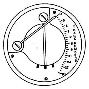
Left: The pilot's combined Track and Course meter.
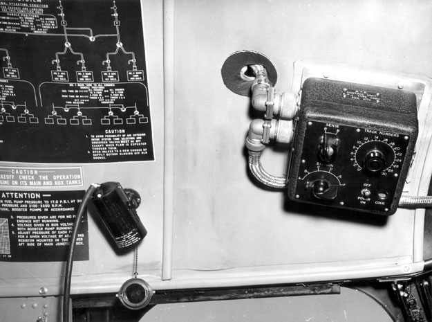
Below: The MTRR selector box (right) installed in the cockpit of TAA DC-4 VH-TAD for trials.There are controls to select the appropriate station pair, the desired track to be flown and the track sense.
Australian Trials
The Sydney-Melbourne air route was chosen for the MTR trials. The ground station sites were at the terminal points, and at one intermediate point, Yass, 145 miles (240 Km) from Sydney. The choice of Yass was determined by two features: firstly, it was situated in mountainous country where accuracy of the MTR under adverse conditions could be investigated and where useful information regarding propagation over such terrain could be obtained; secondly, it was at a suitable distance to provide overlapping coverage with the Sydney stations, so that the behaviour of the airborne equipment when in range two stations simultaneously could be investigated.
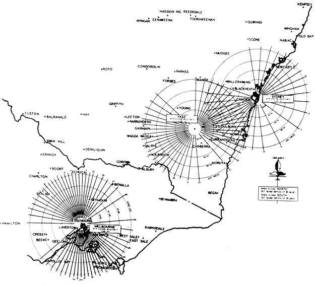
Above: The MTRR trials area on the Melbourne-Sydney air route. The three ground stations were at Melbourne, Yass and Sydney. The numbered tracks from each station can be seen, as well as the unusable segment in line with the two transmitters of each ground station. Note the overlap between the Yass and Sydney beacons.
Technical Specification
| Frequency | 212 MHz |
| Ground Station peak power | 1 kW |
| Pulse length | 1.5 microseconds |
| Pulse repetition frequency | 266 pulses per second |
Two commercial aircraft were fitted for the purposes of the trials with DME and MTR equipment. They were TAA DC-6 VH-TAD and an ANA DC-3. An RAAF C-47 Dakota was also fully equipped and used by the Radiophysics Laboratory for special tests and for demonstrations. During the trials aircraft crews were requested to use the equipment as fully as possible, to record the maximum useful ranges obtained at the heights flown, to use DME to calculate ground speed and estimated time of arrival, and where possible note the accuracy of location of the MTR tracks.
The Radiophysics Laboratory maintained the airborne equipment and the Sydney ground installation. The ground stations at Melbourne and Yass were installed and maintained by DCA. The stations were switched on when requested by the airlines.
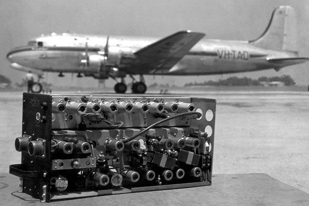
Above: TAA Douglas DC-4 VH-TAD McDouall Stuart was one of two airline aircraft fitted with MTRR receiver equipment for the trials. The other aircraft was an ANA DC-3. A RAAF C-47 was also used for trials work. A DCA DC-3 was equipped with MTRR but went unserviceable and was unable to participate. The photo shows McDouall Stuart at Melbourne/Essendon with an MTRR reciever in the foreground.
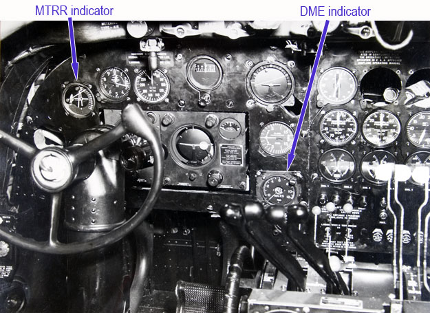
Below: MTRR and DME indicators installed in VH-TAD’s cockpit for the trials. On the MTRR pilot’s instrument, the horizontal needle shows number of the current track that the aircraft is on: the vertical needle shows displacement from the selected track to be flown.
Results of Trials
The results of trials were assessed against the following criteria:
Maximum Range
The majority of flights recorded an effective operating range of 80 to 130 miles (128 to 208 Km). Taking into account errors of observation and conditions of propagation, the study concluded the most suitable separation between stations was a little over 100 miles (160 Km).
The few opportunities the airliners had to check the accuracy of the DME were made when the aircraft flew over recognizable landmarks. The evidence suggested an accuracy of between 2% and 3½%.
Ease of Flying MTR Tracks
Experience gained from the trials indicated that, with experience, pilots could fly on to a track and maintain an accuracy of plus or minus one quarter of the track separation, i.e. about 1% to 1½%.
Outcome
ICAO decided in 1946 to standardize for the immediate future on DME and on the CAA “Omni” range for international use as short-range navigation aids. The choice of the “Omni” range was determined on its omni-directional character and by the prospect of availability of equipment. ICAO also recommended that development of other forms of omni-directional range should continue.
Prototype models, both of airborne and ground equipment, were subsequently developed and tested in Sydney in early 1946, followed by trials on the Sydney to Melbourne air route, and by late 1946 the MTR was demonstrated in Canada to the Radio Technical Division of the Air Navigation Committee of PICAO. Full-scale operational tests continued to be carried out over the period January to May 1947 to May 1949.
The airline crews that participated in the MTR trials were well satisfied with the performance of the equipment as navigation instruments. In January 1950, the DCA Division of Air Navigation Services claimed that operationally, there was little to choose between MTR and the VAR. However, the MTR made ‘extravagant use of the frequency spectrum’ at a time when this was becoming increasingly important. Also, the system had not been developed to the point of commercial production. As so much money and time had been invested in the VAR, there was no question of abandoning it in favour of the MTR.
The principle of Distance Measuring Equipment had been accepted by ICAO for international use and it was decided, as a result of the DME/MTR trials, to proceed with the development in Australia of a nation-wide DME system, operating in the 200 MHz band.
(Photos: CAHS/Ken Dicker)
Back to the main Communications & Navigation index