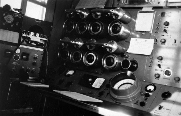
Adcock-type
High Frequency Cathode Ray Direction Finding equipment (HF CR DF) was
installed at selected locations around Australia from 1940 to replace
the earlier MF Bellini-Tosi equipment. Groote Eylandt (seen here, above) was
one of the locations at which it was installed.
An alternative type of Adcock HF DF receiver was the HF-Goniometer receiver which was operated in a similar manner to the MF DF. The Lord Howe Is and Norfolk Is stations had the Goniometer type of equipment.
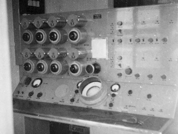
The photo avove shows the HF-CR receiver console. To set up a desired frequency, 8 coils (4 north/south, amplifier top row & 4 east/west, amplifier third row) were installed and 8 capacitors (the large black knobs) were tuned to the frequency. The amplifiers were then balanced and checked with the test antenna signal.
The operator's display was the cathode ray tube at lower centre of the console. The photo below shows another Adcock console at an unkown unit.
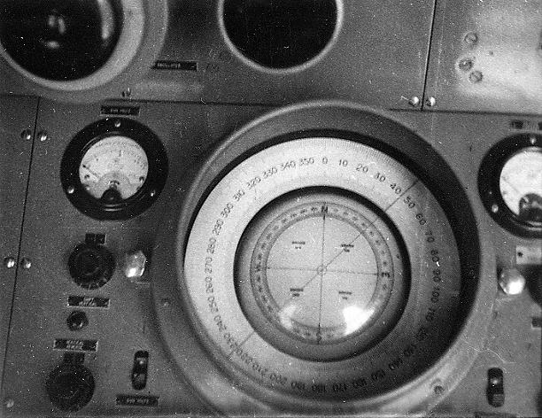
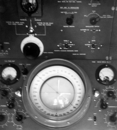
The photos above and below
show the cathode ray tube display, of 5 inches diameter, for the HF
DF. Some tubes had a compass rose engraved on the face of the tube,
as in the upper photo, however this was not essential as the tube could be installed
to align with the engraved outside scale. A received signal would show
as a trace across the diameter of the display and the wire seen in the
photo above at 045 degrees was rotatable to align with the direction of the
trace on the face of the tube.
Bearings taken within 150km radius were accurate and aircraft could 'home' on the DF station when other aids were not available. For aircraft in the range 150-450km radius, bearings were not as accurate as the received signal from the aircraft had travelled over a number of paths which involved reflections from the upper atmosphere.
Operators became highly skilled at interpreting readings on the cathode-ray screen and could tell when bearings were likely to be in error. The operator would qualify his bearings in three classes of accuracy: A - accurate to within two degrees; B - accurate to within five degrees; or C - accurate to within ten degrees. In practice, a class B bearing meant a possible presentation error of +/-75km at a distance of 900km.
(Photos:
1 & 3-CAHS/Rod Torrington collection; 2 & 4-CAHS collection)
Back to the Communications & Navigation index page
If this page appears without menu bars at top or left, click here